
CNC (computer-numerical-control) machining is a popular term used in industrial and manufacturing applications. Basically, it is a process of subtractive manufacturing that runs on machine tools and computerized controls. This process helps remove material layers from the stock piece (workpiece or blank) for the production of custom-designed parts. CNC machining is an appropriate process for a broad spectrum of materials, such as plastics, metals, foam, composites, glass, and wood. Today, we will talk about the most common CNC milling parts and some important things about this process.
The CNC milling process has evolved from NC (numeric-control) machining process that utilizes punched tape cards. The CNC milling process offers several operations and capabilities, but the basic process principles remain almost the same. The different stages of the CNC milling process include CAD model designing, conversion of CAD file into the CNC program, CNC machine preparation, and machine operation execution, respectively.
Here are the 10 most common CNC milling parts:
This is the grey color iron casting that you see from top to the bottom supporting the machine. In some cases, the bass plays the role of a tank that cuts the fluid.
The column is a big supporting frame connected to the machine base in the vertical order. It basically connects other machine components to the base. There is a hefty casting with the inner spaces that are used for housing the driving motor. This milling part also grips the turret.
This is an important CNC milling part that ensures the rotation of the milling head perfectly alongside the column center.
Placed in the middle of the table and the knee, a screw around the knee top joins the saddle for moving it by power or hand. It makes sure that the workpiece travels on the table’s y-axis.
There is a ‘T-Shape’ opening on the surface where the workpiece can be placed and be protected afterward by the vice. You can also clamp the workpiece directly to the table.
This platform is important because it supports the saddle and the table. It controls and holds the machine’s feed mechanism and provides vertical motion on the z-axis above the workpiece.
This is one of the most common CNC milling parts that get power from the machine’s head, and then transmit it to the arbor. The spindle is one large tube that is located on the column’s upper part.
Arbor is basically the spindle’s extension. Its job is to mount and rotate the cutter.
This CNC milling part supplies the motor’s electrical power to the spindle’s mechanical power.
The front brace offers additional support between the over-hanging arm and the knee. This extra support ensures the firmness of the knee and the arbor.
For the production of custom-designed products or parts, manufacturers use different types of CNC machines and tools. The selection of machines and tools depends on specific machining operations. The equipment may change with application and operation type, but the integration of the software and CNC components always remains the same for all processes.
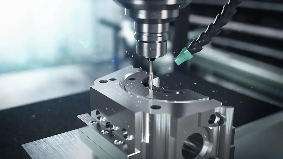
Drilling employs rotation of drill bits for producing workpiece cylindrical holes. The drill bit design allows for waste metal, such as chips, to keep away from the workpiece. There are different types of drill bits. Manufacturers use a single every type for a particular application. For instance, the different types of drill bits include peck drills, spotting drills, chucking reamers, and screw machine drills.
Generally, the process of CNC drilling also uses drill presses (CNC-enabled), which are specially for performing drilling operations. However, milling, tapping, or turning machines can also perform the operation.
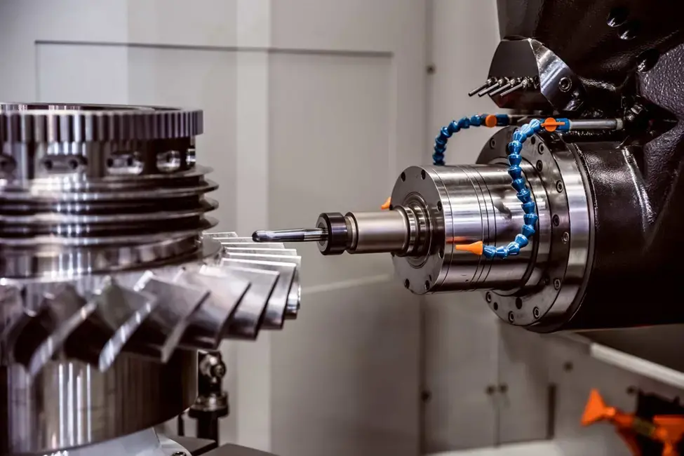
Milling makes use of the rotation of multi-point tools of cutting for shaping the workpiece. These tools are vertically or horizontally oriented and they include chamfer mills, helical mills, and end mills. The process of CNC milling also employs milling machinery (CNC-enabled) that can be vertically or horizontally oriented.
The basic mills have the capability of 3-axis movements, having more complex models accommodating the additional axes. The available mill types include omniversal milling, universal milling, plain milling, and hand milling.
Turning uses the single-point tools of cutting for material removal from the rotating workpiece. Moreover, the turning tool design varies according to a specific application with available tools for facing, finishing, roughing, forming, parting, grooving, undercutting, and threading applications.
The process of CNC turning also makes use of lathes or the turning machines that are CNC-enabled. The available lathes types include special-purpose lathes, engine lathes, and turret lathes.
The CNC or computer numerical control machines come in desktop and standard models. A standard CNC machine is the traditional industry standard machine that manufacturers use to perform particular machine operations, like drill presses. It can also perform various operations, like turning and milling machines.
On the other hand, a desktop CNC machine is a smaller machine with less weight and resemblance of its larger counterparts. A desktop model also typically handles the softer materials, like plastic and foam and smaller parts. These machines are best for light-moderate production outputs. Different types of desktop machines include plotter-sized milling machines and laser cutters, and benchtop or desktop lathes.
The CNC milling process is seemly right for various engineering materials, such as:
The best material selection for a specific manufacturing application depends majorly on the specific manufacturing application as well as its specifications. Most of the materials can be machine-processed because they can tolerate the machining process. These materials have ample hardness, shear strength, tensile strength, and temperature and chemical resistance.
The material and physical properties of the workpiece define the optimal cutting feed ratio, cutting speed, and cut depth.
The broad range of operations and capabilities of the CNC milling process helps in finding applications in different industries. Such industries include automotive, construction, agriculture, and aerospace for the production of different products, like hydraulic components, shafts, and screws.
Despite the customizability and versatility of the process some heavy or large components manufacturing may become a bigger challenge than the others.
The CNC milling process uses software programs for optimization, accuracy, and the precision of a custom-designed product or part. Such software programs include CAD, CAE, and CAM.
CAD (computer-aided design) is a program that manufacturers use for drafting and production of 3D solid or 2D vector part and the surface renderings. This program also drafts ad produces the essential technical specification and documentation linked with the product or part. In addition, this program generates a model design that the CAM program usually use for the creation of the needed machine program.
CAE (computer-aided engineering program is useful for the engineers for analysis, processing, and the post-processing stages of the development process. This software also provides helping support tools needed for analysis operations, like design, planning, simulation, repair, and diagnosis. There are different types of CAE programs, including MDB, CFD, and FEA.
CAM (computer-aided manufacturing) program extracts technical details from CAD model to produce machine program required to operate a CNC machine. It also manipulates tooling for the production of a custom-designed product. This program helps CNC machines run without the assistance of an operator. It also automates the final product evaluation.
In order to learn more, Contact Us Today!
CNC Router Parts Kit: 18 Steps to Build a CNC Router
How CNC Precision Engineering Enhances Quality And Performance